
The Xteink X4 is a tiny eink ereader which is pretty affordable, and definitely very pocketable. At around £44 from Aliexpress I took the plunge.
One big plus that I had read about was that there are actively developed open source firmwares available for this device, most notably Crosspoint Reader. The supplied firmwares are pretty naff and also mine and most of these come out of the box setup with Chinese localisation. So to be honest, beyond just booting the device to check it worked I immediately flashed Crosspoint reader onto it within seconds. Flashing Crosspoint Reader is incredibly simple as there is a web flashing tool. Simply USB your device to your computer, point a chrome based browser at this website and click flash! Simple.


Resistor Color Code Calculator is an interactive online Calculator to calculate the resistance value based on color bands or color-coded stripes on a resistor. //
EIA PREFERRED OR STANDARD RESISTOR VALUE SERIES
E SERIES TOLERANCE
(SIG FIGS) NUMBER OF VALUES IN EACH DECADE

About MarVac
Marvac Electronics is a full-line distributor of electronic components, tools, wire and cable, audio and video product, wire management, and much more. Being founded in 1965, we have proudly celebrated the chance to serve Costa Mesa and the greater Orange County area for over fifty-five years. We are your one-stop, local, family-owned & operated electronics supply store; carrying a large selection of over 4,000+ products with new products added to our storefront and website every day. Our customer care and the providing of satisfaction-guaranteed products is at the forefront of our business and of the utmost importance
We specialize in purchasing inventory lots directly from manufacturers and companies that build electronic equipment. We also have sources that offer us unique and custom parts that you will not find anywhere else. Often we are able to get excess parts inventory from manufacturers who are discontinuing a current product and are liquidating their inventories. We pass the savings on directly to our customers. We carry many of the same products that you will find at a distributor but at a fraction of the price!
Our inventory is constantly changing. Every day, new inventory arrives at our warehouse.
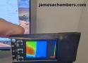
I recently ordered a bunch of new Stemma QT devices including the Adafruit ESP32-S3 Reverse TFT Feather and a MLX90640 IR camera module that I wanted to turn into a DIY thermal camera. I wanted it to be small and battery powered.
In this guide I’ll show you the parts I used to build it as well as the code. Let’s get started!
- It should be both free and open source.
- The file format should be open or well-documented for future migration options.
- It should be multi-platform: in order to be proposed as a standard, anybody must be able to use it. The program has to run on at least Windows and Linux, preferably including Mac OS.
- It should have a (large) standard collection of electric/electronic components, with an extensible library: this way it will not be necessary to draw components from scratch, and, just in case, it will be necessary to do it just once.
- Connections should be better than just lines. They should attach to components, default to right angles, move when the components are moved, autoroute around objects, and so on.
- It should not require the user to learn a great deal of distracting or convoluted methods to draw schematics.
- It should have Bezier curves to allow the creation of good audio curves, since most weighting curves are specified by points, not by an equation or circuit model.
- It has to help the schematic drawing with the option to "snap" components to a grid (otherwise it will be hard to make a precise drawing).
- Optional: It should be part of a complete, easy to use, drawing package, not just for circuit diagrams (though a 'circuit mode' might be good).
The designers of the NTSC system knew theoretically that it would be possible to properly separate Y and C, but did not have a cost-effective way to do it in the early years. In fact, the more sophisticated methods of separation through "comb filters" did not arrive in the market until the late 70's, more than 20 years after the system was adopted.
So, early television receivers used the notch/bandpass filter system for Y/C separation because the method is low cost and easily implemented with reasonable results. In many situations, that approach is used today. In fact, most all of the digital decoders on the market automatically switch back-and-forth between notch/bandpass and combing as required. Watching a VHS tape? You'll most likely be operating in the notch/bandpass mode even if you have a comb filter in your display. Why is it called a notch/bandpass filter?
Bill says:
July 13, 2025 at 6:30 pm
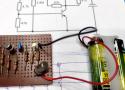
For many years the go-to for timebase generation was the unijunction transistor. You can make a nice sawtooth generator relaxation oscillator with just a battery, UJT, three resistors and one capacitor. The linearity of the ramp is quite good.
Here’s an example: https://www.tutorialspoint.com/pulse_circuits/pulse_circuits_ujt_as_relaxation_oscillator.htm

How Enrico Tedeschi built a collection of over 10.000 artifacts, saved the Marconi Collection, and created the first Sinclair Exhibition. //
Enrico Tedeschi’s legacy: A life-long devoted to researching, collecting, studying, and catalouging consumer electronics. //
“Collecting should not be just amassing the largest possible number of artifacts and memorabilia but also and mainly for the research and understanding of how, when, why, and who invented and produced what, and the social impact and consequences that these products had on the life of millions of people. Collecting should be a way of learning, growing, and self-improvement, and not just a hobby, or an investment,” Enrico Tedeschi wrote in the Introduction of his 1999 self-published book, The Magic of Sony.
How long does it take for your 400mA multimeter fuse to blow at 600mA?
Grab a chair and watch!
The amazing unpredictability of fusing current ratings at low overloads.

The Flipper Zero is basically a two-way remote control that can receive, read, store and transmit a variety of wireless signals. There are plenty of other devices that can do some of these things, but the Flipper puts them all together. Plus, it’s easy to understand—anyone could pick one up and use it to read an NFC card, listen in on someone else's walkie-talkie conversation, or turn off the TV at their neighbor’s house. The Flipper Zero’s gamified presentation (and actual games) and ease-of-use could be seen as a means to demystify the technology that surrounds us, or it could be seen as a way of giving people with limited knowledge a powerful tool to cause chaos. It’s all about how you use it.

A revolutionary current clamp engineered for powerful performance and unmatched portability.
Pokit Innovations
All types of resistors have their own resistor symbols which are used when a circuit diagram is drawn. This page will explain the different standards which are used for resistor symbols and display the most common symbols.

Have you ever turned on a transformer and heard a loud humming sound? What about having a blown fuse or tripped circuit breaker? These signs can all indicate transformer inrush current.
Transformer inrush current describes a spike in current that occurs when you initially turn on your transformer. This spike can be up to 10 times higher than normal current. Why does inrush current occur? It can happen because large transformers demand a huge amount of current when energized. Until the inductive resistance and magnetic field builds, they essentially act as short circuits. //
What is a practical solution to this problem? One convenient way to limit inrush current in a transformer is by using an NTC thermistor. The photo below shows an NTC thermistor placed in the circuit board to provide optimal inrush protection (Figure 2).
Transformer inrush current limiter in circuit
Figure 2: The NTC thermistor is placed in series with the input line to limit inrush current in a transformer.
Transformer Inrush Current Calculation
Here at Ametherm, we have a calculation that we use to help our customers select the right NTC thermistor part number. We thought we would share this with you so you can do the math for yourself, if you feel so inclined.
The 7 step process below will walk you through the calculation we performed for a 40VA transformer. You can apply these calculations to your own transformer as well.
How do I Select the Right Inrush Current Limiter for My Application?
Inrush current limiters are designed with different characteristics like resistance versus temperature curve to accommodate numerous applications. Because of this, it is necessary to make some calculations based on your system requirements to select the best inrush current limiter for your needs.
If the AC wave is going through its zero value, the current drawn will be very high and exceed the saturation current (Figure 1). In this situation, transformer inrush current protection becomes necessary to keep the transformer functioning properly.
Transformer inrush current wave
Figure 1: A transformer draws inrush current that can exceed saturation current affecting the magnetic property of the core.
Solution to Transformer Inrush Current
What is a practical solution to this problem? One convenient way to limit inrush current in a transformer is by using an NTC thermistor.

A time delay circuit, consisting of a relay and timer, can be employed to take the inrush current limiter out of the circuit as soon as the inrush current has passed through, allowing the inrush current limiter to begin to cool down much sooner. A great example of how this is done can be found at instructables.com, showing how to create this time delay when the inrush current limiter needs a little rest.

Large transformers have a huge current demand when they are initially turned on. This is because, until the magnetic field and inductive resistance builds, they are essentially short circuits. For example, you may have turned on some large tool or appliance and heard an initial large "HUMMMMMMM". That is the transformer say "Ow". The circuit breaker for that outlet might also go "Whoa, what are you doing!"
The transformer above (Avel Y236907 800VA 45V+45V Toroidal Transformer), for example, will try to draw over 100 Amps on the first cycle of 60 Hz Power.
To keep a large transformer from being damaged at turn-on (and to keep it from saying "ow"), or to keep a breaker from popping, you put in an inrush current limiter circuit. This Instructable will detail how to do that.

Making an oscilloscope is relatively easy, while making a very fast oscilloscope is hard. There’s a trick that converts a mundane instrument into a very fast one, it’s been around since the 1950s, and [CuriousMarc] has a video explaining it with an instrument from the 1960s. The diode sampler is the electronic equivalent of a stroboscope, capturing parts of multiple cycle of a waveform to give a much-slowed-down representation of it on the screen. How it works is both extremely simple, and also exceptionally clever as some genius-level high-speed tricks are used to push it to the limit. We’ve put the video below the break.
[Marc] has a Keysight 100 MHz ‘scope and the sampler allows him to use it to show 4 GHz. Inside the instrument is a pair of sample-and-hold circuits using fast diodes as RF switches, triggered by very low-rise-time short pulses. Clever tricks abound, such as using the diode pair to cancel out pulse leakage finding its way back to the source. To complete this black magic, an RF-tuned stub is utilized to help filter the pulses and further remove slower components.
It’s thus interesting on more than one level to find a promotional film from the mid 1970s showcasing VEB Fernsehgerätewerk Stassfurt (German, Anglophones will need to enable subtitle translation), the factory which produced televisions for East Germans. It provides a pretty comprehensive look at how a 1970s TV set was made, gives us a gateway into the East German consumer electronics business as a whole, and a chance to see how the East Germany preferred to see itself. https://www.youtube.com/watch?v=P0xMK6UZBys //
The film is at pains to talk about the factory as a part of the idealised community of a socialist state, and we’re given a tour of the workers’ facilities to a backdrop of some choice pieces of music. References to the collective and some of the Communist apparatus abound, and finally we’re shown the factory’s Order of Karl Marx. As far as it goes then we Westerners finally get to see the lives of each genosse, but only through an authorised lens.
The TVs made at Stassfurt were sold under the RFT East German technology combine brand, and the factory continued in operation through the period of German re-unification. Given that many former East German businesses collapsed with the fall of the Wall, and that the European consumer electronics industry all but imploded in the period following the 1990s then, it’s something of a surprise to find that it survives today, albeit in a much reduced form. The plant is now owned by the German company TechniSat, and manufactures the latest-spec digital TVs. //
As a juxtaposition of how a communist TV factory saw itself, have a watch of a capitalist one doing a bit of self-promotion.
https://hackaday.com/2017/12/29/retrotechtacular-1950s-televisions-were-beasts/#more-287834